





Integrating an RTK module for drone platforms is rarely limited by the module’s headline accuracy figure. On a real airframe, three constraints decide the outcome: how much weight the platform can spare, how much current the flight battery can release, and where the antenna can physically sit without ending up inside a field of interference. This guide follows those constraints in the order they appear during a UAV build — module selection, antenna placement, correction data, mechanical and thermal integration, and verification before the first flight.
Why Drone Platforms Move to RTK
Standalone single-point GNSS delivers metre-level absolute accuracy. That is enough for manual flight and rough tracking, but it is not enough for the missions most commercial UAVs now fly: photogrammetric mapping, crop spraying with controlled overlap, power-line and asset inspection, delivery and precision landing. RTK lifts the solution from metre level to centimetre level by applying corrections from a reference station to the rover’s carrier-phase observations in real time.
The operational value on an aircraft is repeatability. The same waypoint, the same spray line and the same landing pad keep their coordinates across flights, batteries and days — which is what makes automated mission planning and change detection possible in the first place.
What Drone Integration Demands From a GNSS Module
Four constraints dominate module choice on a UAV, and they usually conflict with each other:
- Weight and volume. On a multi-rotor, every gram trades against payload and endurance. A module that integrates its own antenna removes a separate feed line, connector and mounting bracket from the bill of materials — often a larger saving than the module itself.
- Power and heat. The GNSS feed competes with the flight controller, radio link and payload for a shared battery rail. Low average current matters most on fixed-wing and long-endurance platforms, where the module runs for the whole flight.
- Update rate and latency. Mapping and spraying work well at 1–5 Hz. Aggressive manoeuvres, gimbal stabilisation and high-speed survey flights need a faster solution update so the controller is not flying on stale position data.
- Interfaces and environment. The module has to speak the flight controller’s language — UART, I²C or CAN — and survive the vibration, temperature swing and airflow of an airframe.
Choosing an RTK Module for Drone Platforms
The three modules below cover the most common UAV integration profiles: a weight-limited airframe that needs receiver and antenna in one housing, a high-dynamics platform that needs a fast solution update, and a long-endurance platform that needs the lowest possible current draw.
JS-RK43-3 — Integrated-Antenna Module for Weight-Limited Airframes
.png?imageMogr2/format/webp)
A dual-band L1+L5 RTK module built for UAV integration, with the antenna already inside the housing. Rover and base station modes are both supported, so the same part can serve as a moving rover or as a local reference on site.
- Envelope: bottom Φ48.00 mm, top Φ43.20 mm, height 37.00 mm
- Weight: under 23.20 g
- RTK accuracy: 1.0 cm + 1 ppm horizontal, navigation update up to 10 Hz
- Power: 45–65 mA average at 5.0 V, −40 °C to +70 °C operation
- Interfaces: 2 × UART plus 1 × I²C
- Interference: six anti-tone jamming filters for L1/L5, with interference detection and multipath compensation
JS-ARK28-3 — 20 Hz Update Rate for High-Dynamics Flight
.png?imageMogr2/format/webp)
A dual-band module for platforms that need a faster solution update and an on-board heading reference. Alongside the L1+L5 stacked passive antenna, it carries its own TCXO, LNA, SAW filter and RTC, which simplifies integration on a tightly packed airframe.
- RTK accuracy: 1.0 cm + 1 ppm CEP horizontal, 1.5 cm + 1 ppm CEP vertical
- Update rate: up to 20 Hz (1 Hz default; 20 Hz requires specific firmware support)
- Interfaces: UART (TXD/RXD) and I²C (SCL/SDA)
- Magnetometer: IST8310 by default (address 0x0F), with QMC5883L (0x0D) and VCM5883 (0x0C) as options
- On-board: dual-band stacked passive antenna, TCXO, LNA, SAW filter, RTC
JS-RK26-3 — 20 mA Module for Long-Endurance Platforms
.png?imageMogr2/format/webp)
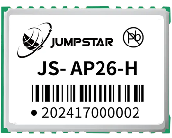
A 16 × 12 mm class module for fixed-wing and long-endurance airframes, where current draw over a multi-hour flight matters more than housing convenience. It works with either a passive antenna or an active antenna, which gives the integrator freedom to place the radiating element where the airframe allows.
- Package: 16.2 × 12.2 × 2.3 mm ±0.3 mm
- Power: 20 mA typical at 3.3 V, 14 µA standby
- RTK accuracy: 1.0 cm + 1 ppm CEP horizontal, 1.5 cm + 1 ppm CEP vertical
- Interfaces: UART, I²C, TIMEPULSE (PPS), RESET_N, VCC_RF and VBAT backup
- Antenna support: passive or active, 15–30 dB recommended active gain
- Temperature: −40 °C to +85 °C operating and storage
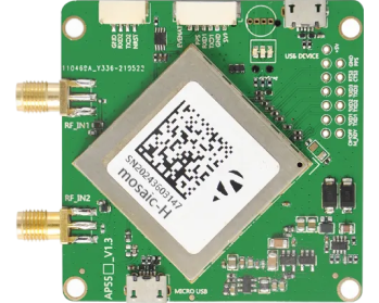
Platforms that also need a heading solution — where the aircraft must know which way it is pointing, not only where it is — are better served by a dual-antenna arrangement. JUMPSTAR’s heading and positioning boards cover that case, while the wider high-precision RTK module family covers platforms that need more channels, extra frequency bands or base station capability.
Antenna Placement Decides the Final Accuracy
A module can only report what the antenna delivers, which is why antenna placement decides the accuracy the aircraft actually achieves. The rules are consistent regardless of airframe type:
- Clear sky view. Keep the antenna above every conductive surface, with an unobstructed view down to low elevation angles. Motors, ESCs, batteries, camera gimbals and carbon fibre all degrade the pattern when they sit too close.
- Ground plane. A stable reference plane under the radiating element improves gain at low elevation and reduces sensitivity to the airframe below it.
- Feed line and connector discipline. Keep coaxial runs short, avoid sharp bends and protect connectors from moisture and vibration. A marginal connector looks exactly like a slow accuracy loss.
- Matched frequency support. The antenna must cover the bands the module tracks. Pairing a dual-band module with a single-band antenna silently removes the interference and multipath benefits those extra frequencies were chosen for.
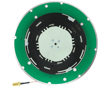
Airframes with limited mounting real estate often use a compact helical design; the UAV and helical antenna range is built for that constraint.
Correction Data: Local Base Station or Network RTK
RTK needs a correction stream, and the drone programme has to decide where it comes from. A local base station set up near the work area gives independence from cellular coverage and keeps latency predictable, which suits remote farmland, long corridors and fixed test ranges. A network RTK service removes the need to deploy and guard a reference receiver, which suits fragmented urban tasks and small sites.
Whichever path is chosen, two engineering details deserve attention. First, corrections must reach the module intact — over a dedicated serial link, or forwarded by the flight controller over the telemetry radio. Second, the base position itself must be known or surveyed in, otherwise the whole system is centimetre-accurate relative to the wrong point.
Mechanical, Thermal and EMI Integration
An airframe is an electrically noisy, vibrating environment, and the GNSS chain is one of the quietest signals on board. Mount the module on a surface that damps high-frequency vibration without introducing soft, springy movement that would confuse the flight controller’s inertial sensors. Keep the GNSS harness away from motor and ESC power leads, and separate it from video transmitters — radiated noise from a video link is a classic cause of a solution that degrades only when the camera is running.
Thermally, most modules specify a wide industrial range, but the surrounding components often do not. Give the module airflow rather than insulation, and check the temperature it reaches inside a closed canopy on a hot day with the payload running — that is the condition that reveals a marginal design.
Verifying Accuracy Before You Fly
Bench checks catch integration mistakes long before they become flight incidents. Confirm the module reaches a fixed solution and holds it, then compare a known point on the ground against the reported coordinate. Repeat the measurement at different times of day to see how satellite geometry affects the result. Log the solution state, the number of satellites used and the baseline distance alongside the coordinates — when a later flight shows a discrepancy, that log is what tells you whether the cause was the sky, the corrections or the airframe.
Conclusion
Choosing an RTK module for drone integration is a systems problem rather than a specification contest. The module has to fit the weight, power and interface budget of the airframe; the antenna has to sit where the pattern stays clean; the correction stream has to arrive intact; and the result has to be verified on the bench before it is trusted in the air. Get those four right and centimetre-level positioning stops being a claim on a datasheet and becomes a repeatable property of the aircraft.
JUMPSTAR has supplied GNSS modules and antennas for UAV integration for more than a decade, from integrated-antenna RTK modules to compact low-power parts and full-frequency antenna families. The GNSS module range, along with engineering support on selection and configuration, is available to teams building RTK platforms.
.png?imageMogr2/format/webp)
.png?imageMogr2/format/webp)
.png?imageMogr2/format/webp)
.png?imageMogr2/format/webp)