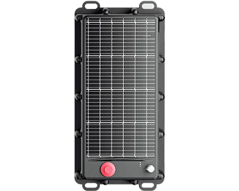
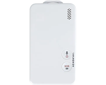
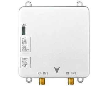







Airport ground support operations depend on the coordinated movement of many vehicle types: passenger shuttle buses, aircraft towing vehicles, baggage tractors, refuelling units, maintenance vehicles, ground power units and de-icing equipment. Each works inside a shared, tightly scheduled apron where operators need reliable visibility of where vehicles are and how they are moving. GNSS RTK for airport ground support vehicles is one technology that can supply that location layer, where suitable GNSS reception and correction conditions exist. This guide covers the engineering requirements and how positioning data feeds fleet coordination.
Positioning and Coordination Challenges in Airport Ground Support Operations
An apron is a large, open but heavily obstructed operating area. Aircraft fuselages, terminal structures, jet bridges and other vehicles create obstruction patterns that change minute by minute, so a setup that works on an open taxiway may behave differently beside a parked wide-body aircraft.
Coordination adds a second difficulty. Passenger transport, baggage, fuelling and technical services are handled by different teams. Without a shared location picture, dispatching relies on radio calls and manual reporting, making vehicle location and task duration hard to confirm.
Why GNSS RTK for Airport Ground Support Vehicles Matters
Standard GNSS positioning is adequate for knowing which airport a vehicle is at. Apron operations ask a harder question: which stand, which service road, which side of the aircraft. RTK improves the answer by combining carrier-phase observations with correction data from a base station or correction service, supporting positioning precise enough to place a vehicle on a detailed airfield map rather than a street map.
That precision makes several workflows practical. Geofences around stands, service roads and restricted zones let entries and exits be logged automatically. Fleet platforms receive cleaner location input for dispatching, utilisation analysis and route history, and automation projects gain one input a control system can build on.
None of this is unconditional. RTK performance on an apron depends on satellite visibility, correction availability, multipath from metal structures, antenna installation, receiver capability and coverage. Centimetre-level figures are a specification under defined conditions, not a guarantee beside every aircraft.
Key Requirements for GNSS RTK Terminals Used in Airport Vehicles
Vehicle-mounted terminal selection is narrower than a general receiver checklist. These points most often decide whether a deployment works in practice.
- Positioning performance: Datasheet accuracy is measured under defined conditions; field results differ with sky view, correction quality and multipath.
- Signal availability: How the receiver behaves when aircraft or buildings block part of the sky, and whether multi-constellation tracking holds a solution.
- Heading and attitude: Some tasks care which way equipment points, not only where it is, which decides the antenna architecture.
- Motion sensing: Inertial support can bridge short interruptions near stands; its limits should be verified, not assumed.
- Electrical compatibility: Ground support equipment spans 12 V and 24 V systems, so input range and consumption must match the fleet.
- Communication and interfaces: Apron cellular coverage, protocol compatibility with the existing platform, and ports for peripherals.
- Environment and maintainability: Temperature range, sealing, vibration, mounting, local storage and remote configuration affect lifetime cost.
JUMPSTAR A12 RTK Vehicle-Mounted Positioning Terminal
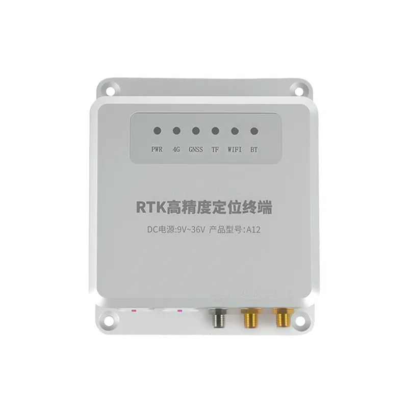
The JUMPSTAR A12 RTK vehicle-mounted positioning terminal is a full-band RTK terminal designed for vehicle installation, with TF card and SIM card slots. The features below are those confirmed on the official product page.
.png?imageMogr2/format/webp)
.png?imageMogr2/format/webp)
High-Precision Positioning for Vehicle Operations
The A12 is specified with RTK horizontal accuracy of 2 cm ± 1 ppm, using the NTRIP protocol and RTCM 3.0–3.3 differential data. It tracks GPS, BDS-2/3, GLONASS, Galileo and QZSS across their full bands, with a configurable update rate of 1–10 Hz, which is enough to feed a detailed airfield map continuously.
Navigation, Motion and Attitude Capabilities
A dual-antenna configuration outputs heading and pitch, specified as (0.15/R)° and (0.25/R)° where R is the baseline length in metres. Heading accuracy therefore improves as antenna separation increases, which puts mounting geometry inside the accuracy budget. The integrated IMU is specified to hold centimetre-level positioning for 3 seconds and metre-level positioning for 10 seconds after GNSS signal loss — a bridge for short outages, not a substitute for satellite reception.
Vehicle-Mounted Integration
Published integration features include a DC 9–36 V input covering light and heavy vehicle electrical systems, operating current of ≤300 mA at 12 V, and a 3.7 V / 350 mAh backup battery giving at least 10 minutes of operation after vehicle power loss. Communication is 4G Cat.1 with TCP and UDP, the JT/T 808-2013 protocol and dual-IP transmission. The aluminium alloy housing is IP66 rated for −20 °C to +75 °C. Expansion covers CAN, RS232, TTS and GPIO, with SMS or platform configuration and FOTA upgrade.
Support for Fleet Management and Operational Systems
The A12 supplies position, attitude, timing and peripheral data over the cellular link. Dispatching logic, geofence rules, reporting and optimisation sit in the fleet management platform, not in the terminal.
| Function | Positioning terminal | Fleet management platform |
|---|---|---|
| Position, heading and time data | Provides | Consumes |
| Geofence definition and rules | Not defined here | Configured and evaluated |
| Dispatch decisions | Not performed | Performed |
| Historical records and reporting | Local logging and upload | Long-term archive and analysis |
Potential Airport Ground Support Vehicle Applications
The categories below describe where accurate positioning is technically relevant, not records of specific deployments.
Passenger Shuttle and Service Vehicles
Shuttles run repeating routes between terminals and remote stands. Location data lets a dispatch platform compare actual against scheduled position and supports headway monitoring.
Aircraft Towing and Ground Handling Vehicles
Towing and pushback involve precise, slow movement close to aircraft, where a positioning record supports documentation and workflow visibility. The A12 is not certified as an aircraft towing safety system; safety-related use falls under the operator's own approvals.
Baggage and Cargo Support Vehicles
Baggage tractors and cargo transporters move constantly between terminal, stands and service areas. Tracking shows dwell times and where equipment is available when a task is assigned.
Maintenance and Airport Service Vehicles
Ground power, refuelling, de-icing and maintenance units work to their own schedules across dispersed locations. Positioning data supports route management, response visibility and automatic records of area coverage.
Future Automation and Autonomous Ground Operations
Reliable positioning data is one component of an automation architecture and rarely the limiting one. Automated apron operations also depend on vehicle control, obstacle detection, safety interlocks, site mapping, communications, application software and operational validation. The A12 is a positioning terminal, not an autonomous driving system.
How GNSS RTK Can Support Airport Fleet Coordination
Positioning data can provide an important input to a broader fleet management system. Location visibility gives dispatchers a current fleet picture; geofencing records stand occupancy, zone entry and restricted access automatically; route history supports review of turnaround times; dispatching and utilisation analysis compare planned against actual movement.
The business outcome comes from the complete system: software logic, procedures and deployment environment all contribute, and a terminal supplies data rather than results.
What Should Buyers Confirm Before Selecting a GNSS RTK Terminal?
Verify the following with the supplier rather than assuming them from a product name.
- Requirements: Required accuracy, correction source and its availability on site, and the constellations and bands the project needs.
- Antenna and attitude: Antenna compatibility, mounting position and baseline length, and whether heading output is genuinely required.
- Sensing: Whether inertial support is needed and the expected behaviour during signal interruptions.
- Electrical fit: Vehicle voltage range, current draw, backup power behaviour and electrical environment.
- Connectivity and interfaces: Network coverage, transmission protocols, external ports, storage and remote management.
- Environment and lifecycle: Protection rating, temperature range, platform compatibility, support and supply continuity.
- Pilot testing: A trial on representative vehicles in representative apron areas before fleet-wide rollout.
Deployment Considerations for Airport GNSS RTK Applications
Installation is the start of a deployment project, not the whole of it. Antenna placement decides how much sky the receiver sees and how much multipath reaches it, which on vehicles with large metal structures is often the most influential decision. Correction coverage, latency and apron cellular signal should be verified across the operating areas, not only at the maintenance base.
A deployment also requires electrical integration, secure mounting, service access, field testing in representative areas, integration with the existing fleet platform, and safety validation with the relevant airport teams. Airports usually apply site-specific rules to vehicle equipment and testing, so early coordination with operations is cheaper than late adjustment.
Why Work with JUMPSTAR for GNSS Positioning Solutions?
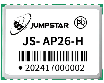
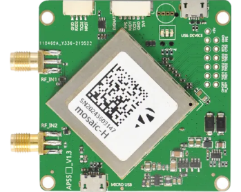
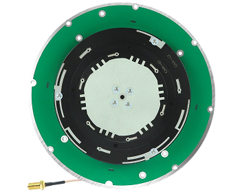
JUMPSTAR develops GNSS hardware across the modules, boards, antennas and terminals a vehicle positioning project needs, including GNSS modules, GNSS OEM boards, GNSS antennas, RTK receivers and systems, tracking and telematics terminals and evaluation kits. Antenna options include vehicle and fleet antennas, which matter because antenna choice and placement carry much of the positioning performance in a vehicle installation.
For OEM and integration projects, the useful conversation is about requirements: which accuracy the application needs, what correction source will be used, how attitude data will be consumed and which interfaces the existing platform expects.
Conclusion
Airport ground support operations combine large, obstructed areas with many vehicle types and several dispatch teams, which makes accurate location data both useful and difficult to obtain. GNSS RTK for airport ground support vehicles can supply that data where reception and correction conditions allow, and terminals such as the A12 provide the vehicle-side hardware, including heading, attitude and short-term inertial support.
Results still depend on antenna installation, correction availability, integration and field testing. Positioning data is one part of a complete operational system, and the fleet platform and procedures decide the business outcome. Teams evaluating this technology can review the A12 specification or contact JUMPSTAR to discuss their requirements.
.png?imageMogr2/format/webp)
.png?imageMogr2/format/webp)