





Two teams can buy the same RTK equipment and get very different results. One team holds a fixed solution all day; the other fights slow initialization, drifting points and correction dropouts. In most cases the difference is not hardware quality — it is matching, configuration, environment and field procedure. This guide brings together RTK GNSS best practices for preventing those problems, and a symptom-by-symptom troubleshooting section for diagnosing them when they still appear. It is written for engineers and field operators across surveying, precision agriculture, UAV operations, ports, airports and industrial sites.
How RTK Positioning Works — and What Each Solution State Means
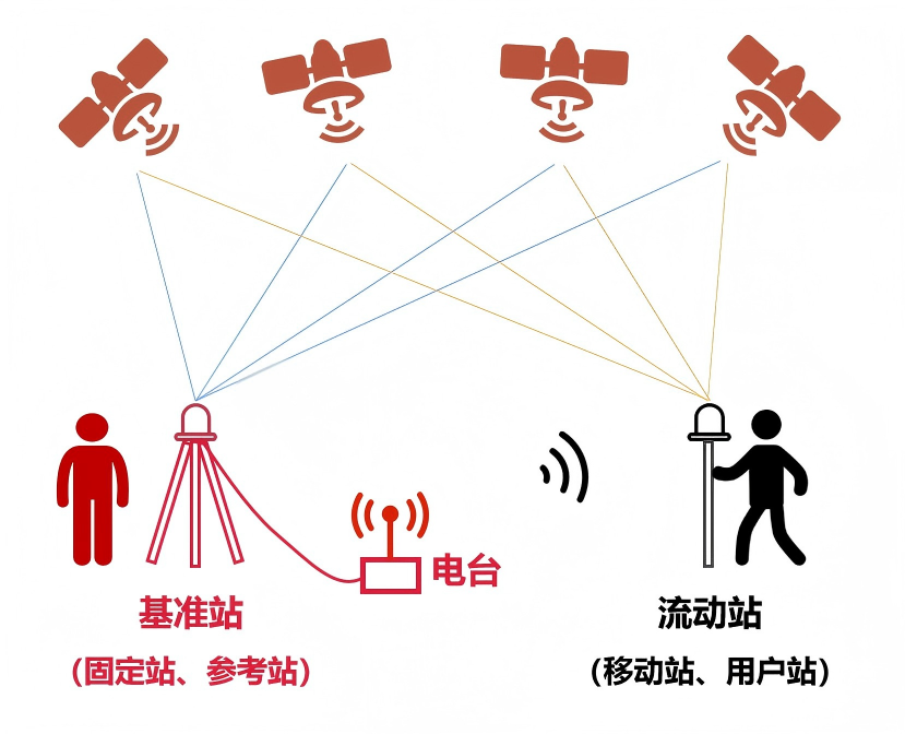
RTK (Real-Time Kinematic) positioning combines carrier-phase observations from a rover receiver with correction data generated by a reference station at a known position, or by a network of reference stations. Because the reference and the rover observe the same satellites under broadly similar atmospheric conditions, the corrections remove most orbit and atmospheric error, lifting accuracy from metre level to centimetre level in real time.
The rover reports one of three solution states, and recognizing them is the starting point for any diagnosis.
| Solution state | What it means | Typical accuracy expectation |
|---|---|---|
| Fixed | Carrier-phase ambiguities resolved; corrections applied consistently | Centimetre-level, suitable for survey-grade work |
| Float | Ambiguities estimated but not fully resolved | Decimetre-level and unstable; not suitable for precision records |
| Single point | No usable differential correction applied | Metre-level standalone positioning |
A stable fixed solution is a system outcome, not a guaranteed property of the receiver. It depends on satellite geometry, signal quality, correction integrity, baseline length and the environment around the antenna — every recommendation below protects one of those links.
Match the Receiver and the Antenna First
The receiver is the processing core; the antenna is the signal entrance. If their frequency support does not match, the system cannot deliver its rated performance — one of the most commonly overlooked issues. Three combinations cover most field mistakes:
- Full-frequency receiver + dual-frequency antenna: the antenna cannot pass the higher-frequency signals (such as L5/B3) the receiver is designed to use, so the system effectively runs as a dual-frequency setup and loses the extra interference rejection and multipath suppression those signals provide — most visible under trees, beside tall buildings or over reflective water.
- Dual-frequency receiver + full-frequency antenna: the extra signals are received but never used, so the added cost, size, weight and power draw bring no accuracy gain — a real penalty on weight-sensitive UAVs and portable kits.
- The general rule: match frequency capability on both ends. Dual-frequency pairs suit routine municipal, farmland and general survey work; full-frequency pairs suit UAV mapping, corridor monitoring and port or airport operations.
Beyond frequency, keep feed lines short and inspect connectors for damage or moisture, and note what sits within a metre of the antenna — metal structures, cab roofs, UAV frames, batteries and flight controllers all distort the antenna pattern if placed too close.
Choose the Right Correction Source: Network RTK or a Local Base Station
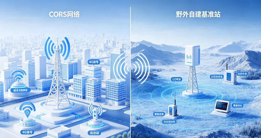
Two correction architectures dominate field practice, and neither is universally better. The right choice follows coverage, communications and the shape of the work.
| Consideration | Network RTK | Local base station |
|---|---|---|
| Correction source | Public or commercial reference network | Base receiver deployed by the user |
| Communication | Cellular data required | Radio link or independent data link |
| Deployment effort | Minimal — subscribe and connect | Base setup, siting and daily checks |
| Coverage | Limited by network footprint and latency | Limited by radio range, but independent of cellular coverage |
| Typical use | Urban surveying, campus work, fragmented small tasks | Remote areas, large farms, long corridors, fixed installations |
Selection should follow correction coverage, communication availability, operating area, accuracy requirement and budget. Some operations use both: network corrections where coverage is reliable, a local base where it is not.
When running a local base station, two matching rules matter. First, the base station's frequency support should meet or exceed the rover's — a base that transmits fewer signals than the rover tracks leads to incomplete corrections and unstable fixes. Second, base and rover should use consistent antenna phase centre correction parameters; mixing PCO/PCV values from different sources introduces a systematic offset.
How Baseline Distance Affects RTK Performance
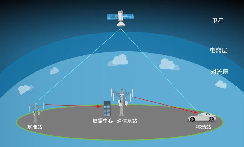
Baseline length — the distance between the reference station and the rover — is one of the most consistently underestimated factors in RTK reliability. As that distance grows, the assumption that base and rover see similar atmospheric conditions weakens. Residual ionospheric and tropospheric error increases, ambiguity resolution becomes less certain, and initialization takes longer or fails more often.
The rate of degradation is not a fixed number. It depends on atmospheric activity, satellite geometry and visibility, the quality and update rate of the correction data, receiver capability, terrain and the surrounding environment. It is more useful to think in terms of operating envelopes than a single universal distance limit: short baselines give the most stable and repeatable results, moderate baselines remain workable for routine work, and longer baselines progressively reduce the margin available for precision tasks.
Practical measures follow from that. Use network corrections or a closer reference where the work demands the highest confidence. On large sites, deploy multiple reference points so no rover works at the far edge of coverage. For error-sensitive operations — water bodies, mountains, high-speed dynamics — tighten the working baseline and validate on site. Record the baseline alongside results so that any accuracy question can be traced back to conditions.
RTK GNSS Troubleshooting: Field Checks by Symptom
Most field problems fall into a small number of recognizable patterns. Work through them in order and change one thing at a time — the commonest mistake is adjusting several settings at once and losing track of what actually helped.
Slow initialization or failure to reach a fixed solution
Possible causes: ephemeris or almanac data out of date after storage; obstruction at the antenna; correction data delayed or not arriving; long baseline. Recommended checks: let the receiver update satellite data over the network before leaving the office; confirm the antenna has a clear sky view and is not shaded by structures or the operator; verify correction latency and format at the rover; compare the working baseline against what the site normally supports.
Fixed solution repeatedly dropping to float
Possible causes: intermittent correction link; multipath from nearby reflective surfaces; marginal satellite visibility; unstable power. Recommended checks: examine the correction link for dropouts and retry latency; raise the antenna above reflective surfaces; review satellite count and geometry in the receiver log; check supply voltage under load, since low voltage often shows up as degraded tracking rather than a clean shutdown.
Position drift or points that do not repeat between sessions
Possible causes: coordinate system or transformation parameters not fixed between jobs; a different reference point or correction source used; an unresolved datum or projection setting. Recommended checks: store the local parameter template and reuse it; verify against a known point before precision work; confirm the same reference configuration across sessions; record the correction source and parameters for each job.
Elevation fluctuating while horizontal position looks stable
Possible causes: height is the component most sensitive to low-elevation multipath and residual atmospheric error; dynamic motion on a moving platform. Recommended checks: enable multipath mitigation; reduce reliance on very low elevation satellites; use inertial blending on vehicle and UAV platforms; avoid working over reflective ground where an alternative site exists.
Correction link connects but data does not arrive correctly
Possible causes: incorrect server address, port or mountpoint; outdated credentials; incompatible correction format; network congestion. Recommended checks: verify settings against the provider's current parameters rather than an old configuration; test the connection before deployment; confirm the correction format the receiver accepts; check whether the link is congested or simply needs restarting.
Radio-linked base station works nearby but drops at distance
Possible causes: channel congestion from other equipment on site; excessive cable loss or a damaged connector; obstacles in the radio path; power settings mismatched to the working distance. Recommended checks: move to a clean channel; inspect connectors for oxidation, moisture or looseness; confirm cable integrity; adjust transmit power to suit the environment and check the base antenna height.
Accuracy degrades in strong electromagnetic environments
Possible causes: interference from high-power electrical equipment, radar or wireless systems; reflection from large metal structures. Recommended checks: route antenna cables away from power cabling, motors and transmitters; switch off non-essential wireless equipment nearby; consider shielded cable runs and interference-resistant antennas for permanent installations.
Temperature-related instability
Possible causes: high ambient temperature affecting electronics; reduced battery capability in cold conditions; thermal drift in uncooled enclosures. Recommended checks: provide shade and ventilation in summer; pre-warm batteries and prefer external power in winter; let the equipment reach thermal equilibrium before starting precision measurements.
Chronic degradation with no obvious fault
Possible causes: water ingress or oxidation at antenna connectors; a strained or kinked feed cable; infrequent use allowing moisture buildup. Recommended checks: inspect and reseat connectors before each job; store equipment in dry conditions and power it up periodically; replace suspect cables rather than continuing to debug around them.
Data quality issues that only appear later
Possible causes: points recorded while the solution was still converging or in float; no record of conditions. Recommended checks: wait for the solution to settle before storing a point; log solution status, satellite count and correction latency with the survey record, so that any later question can be answered from data rather than memory.
When Plain RTK Is Not Enough: IMU Assistance, PPP and Interference Mitigation
Plain RTK has known weak spots: occlusion, weak signal, long baselines and electromagnetic interference. Three complementary technologies address them, each with its own conditions of use.
RTK with IMU assistance. An inertial measurement unit maintains a motion estimate when satellite signals are briefly interrupted — passing under a bridge, flying between obstacles, working beside large structures. The benefit is limited in time: an IMU bridges short outages, it does not replace satellite reception, and it will drift if the outage continues.
PPP for wide-area operation. Precise Point Positioning uses precise satellite orbit and clock products instead of a nearby reference station, which suits very long corridors, remote regions and offshore work. Its trade-off is convergence: a PPP solution generally requires an initialization period before reaching its stated precision, so it suits continuous operation rather than short stop-and-go tasks. Combined RTK/PPP approaches use whichever source is available and reduce dependence on any single correction stream.
Interference and multipath mitigation. Ports, airports, substations and dense industrial sites combine strong electromagnetic noise with abundant metal reflection. Receivers and antennas designed with interference rejection and multipath suppression hold steadier solutions in these settings, but hardware is only part of the answer: antenna siting, cable routing away from power equipment and careful frequency planning matter just as much.

RTK GNSS Best Practices That Prevent Most Field Problems
Diagnosis is easier when the same faults are prevented in the first place. These habits cover the majority of recurring field issues:
- Manage power properly. Low voltage rarely shuts a receiver down; it quietly causes fewer tracked satellites, delayed corrections and float transitions. Start with a full battery, allow a few minutes to warm up and converge, carry spares for all-day work, and prefer external power in cold weather.
- Install the antenna carefully. Mount it vertical with a clear sky view, away from metal, and keep feed lines as short as practical. On UAVs, place the antenna on top of the airframe clear of batteries and flight controllers. Most observed accuracy problems trace back to installation.
- Configure corrections before the work day. Verify server address, port, mountpoint and credentials against the provider's current parameters, test the connection before heading out, and watch correction latency — consistently laggy corrections mean it is time to restart the link or switch sources.
- Know your solution states. Only record data with a fixed solution. Float solutions are unstable at decimetre level and single-point solutions are metre-level with no differential benefit. Wait for convergence after startup; if the fix keeps dropping, improve antenna placement or switch the correction link rather than logging anyway.
- Let points settle. When the solution first reaches fixed, wait a couple of seconds before recording. Avoid collecting points in high wind, with the pole moving, or with people shading the antenna.
- Set up base stations properly. A base is the accuracy datum for the whole job: choose a spot with a full sky view, away from buildings, water and reflective metal, and avoid mounting it too low. For recurring sites, mark a permanent base point so daily setup error disappears. Let the receiver converge before broadcasting corrections.
- Handle elevation and multipath issues. If heights jump while the plane position looks fine, enable multipath mitigation, keep higher-elevation satellites in the solution, and use inertial blending on dynamic platforms — height is the most sensitive component near reflective ground and slopes.
Maintenance Habits That Avoid Chronic Faults
Many stubborn RTK issues are maintenance problems in disguise. Check antenna connectors for water ingress and oxidation before every job — a slowly degrading connector looks like an unexplained accuracy loss. Power up stored equipment periodically to keep boards dry and healthy. And when a receiver that has been idle for months fixes slowly, update its ephemeris data over the network before fieldwork — stale satellite data is the usual culprit, not a fault.
Keep coordinate parameters fixed between sessions. If repeated points drift day to day, the usual cause is an unfixed transformation parameter set or an automatic reset between startups — save the local parameter template and verify against a known point before each job.
Quick Tips by Industry
- UAV mapping: prefer full-frequency receiver-antenna pairs for dynamic stability, and confirm the antenna is mounted clear of the airframe.
- Agriculture: open fields with steady routes suit a cost-effective dual-frequency setup with a radio link for base-to-machine corrections.
- Ports and airports: heavy metal, strong EMI and large moving equipment call for interference-resistant configurations, external antennas and disciplined baseline limits.
- Power and railway fieldwork: in areas without network coverage, a self-built radio-linked base station covers the corridor; for very long routes, evaluate PPP-based or network correction services.
Conclusion
Reliable RTK performance is a system property. It starts with hardware matched to the application, continues with a receiver, antenna and correction source that are properly paired, and depends on choosing an operating method suited to the site — network corrections, a local base, inertial assistance or PPP as conditions require. When problems do appear, work through the symptom checks in order rather than replacing hardware by trial and error. These RTK GNSS best practices do not require more expensive equipment — they require the right configuration for the job, applied consistently.
If you are building high-precision positioning into your own equipment, explore JUMPSTAR's high-precision RTK modules, RTK receivers and systems and GNSS antennas, or contact our technical team to discuss which configuration fits your application.
.png?imageMogr2/format/webp)
.png?imageMogr2/format/webp)