





Surveying and mapping teams spend much of their working life fighting the same problems: large project areas, difficult terrain, repeated measurements, manual data collection and positioning errors that only surface after the crew has left the site. Traditional optical methods demand line of sight between instrument and target, which slows work on wooded slopes, urban corridors and busy construction sites. When a boundary point or a construction stake is recorded in the wrong place, the cost is not just the revisit — it is the ripple of rework through design files, GIS databases and contractor schedules.
Modern surveying increasingly depends on high-precision GNSS positioning to solve these problems, and RTK GNSS technology is the reason why. When suitable correction data and satellite visibility are available, an RTK GNSS receiver or module lets surveying equipment obtain centimeter-level positioning in the field, in real time, without post-processing. This article explains how RTK GNSS works, why accuracy matters in professional surveying and mapping, what affects RTK positioning accuracy in the field, and how equipment manufacturers should evaluate RTK modules and receivers.
What Is RTK GNSS Technology?
RTK stands for Real-Time Kinematic. It is a technique that upgrades standard GNSS positioning from meter-level accuracy to centimeter-level accuracy by using GNSS carrier-phase measurements together with correction data, processed in real time rather than after the fact. Understanding the mechanism helps explain why RTK performs so well in surveying and mapping — and why it occasionally does not.
A standard GNSS receiver measures the code signal from each satellite, which yields positions accurate to a few meters. An RTK-capable receiver additionally measures the phase of the satellite carrier wave, which is far more precise — but ambiguous, because the receiver cannot directly count how many whole cycles lie between the satellite and the antenna. Resolving those integer ambiguities is the core of RTK processing. Once the ambiguities are fixed, the receiver produces an RTK fixed solution with centimeter-level precision.
To fix the ambiguities, the rover needs help. A base station (also called a reference station) sits at a known point and observes the same satellites. Because its position is known, it can calculate the errors in each satellite measurement — atmospheric delays, satellite orbit error, satellite clock error — and broadcast them as correction data to the rover over a radio link or cellular network. Many regions also provide public CORS networks and commercial correction services that replace the private base station entirely. The flow is simple:
The result: the rover applies the corrections, fixes the carrier-phase ambiguities, and outputs a position accurate enough to stake a boundary corner, set a construction point or record a GIS asset — as the measurement happens, not hours later.
Why Accuracy Matters in Surveying and Mapping
Not every positioning task needs centimeters — but most professional surveying and mapping tasks do. GNSS surveying workflows such as boundary surveying, topographic mapping, construction layout and infrastructure surveying all depend on coordinates that hold legal, contractual or engineering meaning. A meter-level position is fine for finding a landmark; it is not fine for recording a property line, setting a bridge pier formwork or capturing utility lines that a contractor will excavate around.
A small positioning error propagates. In boundary surveying, a shifted corner changes the computed parcel area. In construction layout, an offset stake means steel or concrete placed out of tolerance. In utility mapping, a misrecorded valve position becomes an expensive surprise during excavation. In deformation monitoring, the movement being measured may be smaller than the error of a standard receiver. And in digital mapping, every field point flows into GIS and CAD systems, where one bad coordinate contaminates every layer built on it.
That said, accuracy requirements are project-specific. Reconnaissance mapping and asset inventories can tolerate meter-level positions, which is why equipment makers offer both standard-precision and RTK-capable product lines. Precision surveying is about matching the positioning grade to the deliverable — and RTK GNSS is what makes the centimeter grade attainable outdoors, without optical instruments.
How RTK GNSS Improves Surveying Efficiency
Faster Field Data Collection
A crew with RTK-capable GNSS surveying equipment records points at the pace of walking, not at the pace of setting up tripods and back-sights. Large open sites that once required days of traversing can often be covered in a single session, and points that were awkward to reach optically become routine GNSS shots.
Accurate Point Positioning, Once
Because each measurement arrives with centimeter-class confidence, crews stop repeating measurements. Re-shots drop sharply when the field controller shows a fixed solution in real time — the surveyor knows immediately whether a point is good. Fewer repeat visits is one of the most tangible efficiency gains of RTK GNSS in production surveying.
Real-Time Results
Traditional high-accuracy GNSS workflows relied on post-processing: collect raw data all day, download it, and correct it in the office. Real-time kinematic positioning delivers the corrected position on the spot, so crews can verify completeness and quality before leaving the site, and stakeout crews can compare design coordinates against measured coordinates live.
Reduced Manual Work
RTK reduces the manual operations that dominate traditional measurement: fewer instrument setups, fewer prism pole traverses, fewer level runs for routine elevation capture. One person with a rover can often complete work that previously required a two-person team.
Better Digital Mapping
Centimeter-accurate GNSS coordinates import cleanly into GIS, CAD and mapping systems. GNSS mapping workflows benefit twice: field geometry matches design geometry, and downstream teams can trust the captured data without a cleaning pass.
RTK GNSS vs. Standard GNSS for Surveying
The practical difference between a standard receiver and an RTK GNSS receiver comes down to correction data and carrier-phase processing:
| Feature | Standard GNSS | RTK GNSS |
| Typical positioning level | Meter-level | Centimeter-level |
| Correction data | Usually not required | Required (base station or network) |
| Real-time precision | Limited | High (fixed solution) |
| Surveying applications | Basic positioning, navigation | Professional surveying and layout |
| Field efficiency | Moderate | High |
One caution belongs in every selection discussion: actual RTK positioning accuracy depends on the correction source, satellite visibility, antenna quality, atmospheric conditions, multipath and receiver performance. The table describes capability classes, not guaranteed numbers on every site.
What Affects RTK GNSS Surveying Accuracy?
Satellite Visibility
A clear sky view generally improves satellite tracking and positioning geometry. Trees, buildings and cut slopes reduce the number of visible satellites and weaken the geometry the RTK engine uses to fix ambiguities. Open fields fix in seconds; deep urban canyons can struggle to fix at all.
Correction Data Quality
RTK is only as good as its corrections. The quality of the reference station, its baseline distance from the rover, and the latency of the correction link all influence whether the rover holds a fixed solution. Reliable, low-latency correction data is a prerequisite for productive high-precision GNSS surveying.
Multipath
Buildings, vehicles, fences, water surfaces and other reflective structures bounce GNSS signals before they reach the antenna. Multipath corrupts both code and carrier-phase measurements and is one of the most common causes of degraded accuracy or lost fixed solutions on real job sites. Antenna design and receiver filtering are the main defenses.
Atmospheric Conditions
Ionospheric and tropospheric delays affect GNSS measurements, and they grow with baseline length between base and rover. Short baselines largely cancel through the corrections; long baselines and periods of high ionospheric activity can extend initialization times.
Antenna Quality
The antenna is where every measurement begins. Gain pattern, phase center stability, multipath rejection and polarization quality directly affect signal reception and, through it, measurement quality. A high-performance receiver paired with an unsuitable antenna may not deliver the expected field performance — a point that matters enormously in surveying, where millimeters of antenna error translate directly into coordinate error.
Receiver Performance
Finally, the receiver itself. Multi-frequency reception lets the engine correct ionospheric error and fix ambiguities faster; multi-constellation tracking increases the number of usable satellites; RTK processing quality determines initialization time and fix reliability; signal sensitivity and interference mitigation decide how the receiver behaves near heavy machinery, radio towers and other RF noise.
Why Multi-Constellation and Multi-Frequency GNSS Matter
Modern RTK receivers can combine signals from multiple constellations — GPS, BDS, GLONASS, Galileo, QZSS and NavIC — and from multiple frequency bands within each constellation. The specific satellite systems and bands supported by any given product must be confirmed against its official specification, but the system-level benefit is universal.
More tracked satellites mean more measurements, better satellite geometry and improved signal availability, particularly in partially obstructed environments like tree lines, urban corridors and quarry benches. Multi-frequency tracking adds another layer: combining observations from different bands allows the RTK engine to estimate and remove ionospheric error, which speeds up ambiguity resolution and makes the fixed solution more robust. Together, these capabilities let modern RTK GNSS equipment keep working through conditions that would have stopped single-frequency receivers a decade ago.
It is worth being precise: multi-constellation tracking improves availability and geometry; it does not completely eliminate signal loss. A receiver under a bridge deck still sees no satellites. What it does is make the zone between open sky and no sky productive.
RTK GNSS Applications in Surveying and Mapping
Land Surveying
Boundary determination, cadastral work and control-point capture were the first surveying disciplines to adopt RTK, and they remain its core use case: precise coordinates, recorded once, tied to a legal framework.
Construction Surveying
Stakeout and as-built verification run on RTK. Design coordinates go into the controller, the rover guides the crew to each point, and the same rover confirms what was actually built — fast enough to keep pace with concrete pours and steel erection.
Topographic Mapping
Terrain data collection and digital map production benefit from the sheer speed of RTK point capture. Dense spot heights, breaklines and feature codes flow into mapping software with survey-grade accuracy.
Road and Infrastructure Projects
Roads, bridges, pipelines and rail corridors combine long linear geometry with tight tolerances. RTK lets a single crew carry centerline, offset and structural points across kilometers of corridor without accumulating traverse error.
GIS Data Collection
A GNSS receiver for surveying-grade GIS work attaches trustworthy coordinates to assets — manholes, signs, poles, valves — so the GIS layer is accurate at the moment of capture.
Deformation and Monitoring
Fixed monitoring points on dams, slopes, buildings and retaining structures are logged repeatedly over time. Centimeter-class, repeatable positioning is what makes the movement trend visible above the noise.
Choosing an RTK GNSS Receiver for Surveying Equipment
For OEMs and equipment manufacturers building GNSS surveying equipment, receiver selection is a system decision. The factors that matter most:
Positioning accuracy. Compare RTK horizontal and vertical accuracy specifications across candidates, and note how each vendor expresses them (RMS, CEP, or with a ppm baseline term).
Satellite constellation and frequency support. Match supported systems and bands to the regions where the equipment will operate and the environments it will face.
Initialization performance. RTK initialization time and fix reliability determine how much of each workday the crew spends productive versus waiting for a fixed solution.
Update rate. Dynamic platforms — robotic total stations, machine control, UAV surveying payloads — need position updates fast enough for the control loop; static pole work is far less demanding.
Interference and multipath mitigation. Urban sites, industrial plants and construction zones are electromagnetically hostile; anti-interference capability directly affects uptime.
Antenna compatibility. Receiver and antenna must be matched in frequency coverage, gain and mounting; treat the pair as one measurement chain.
Interfaces. Choose from the interfaces your equipment design actually uses — UART, USB, Ethernet, CAN or I2C — and confirm them on the product's official specification.
Size and power consumption. For handhelds, robotic surveying platforms and UAV surveying equipment, mechanical envelope and power budget can eliminate otherwise excellent modules early in selection.
JUMPSTAR RTK GNSS Solutions for Surveying and Mapping
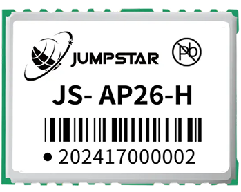
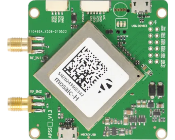
JUMPSTAR provides RTK GNSS modules, GNSS OEM boards, RTK receivers, GNSS antennas and embedded positioning solutions, with OEM integration support for equipment manufacturers and system integrators. Three products illustrate how these building blocks fit surveying and mapping equipment:
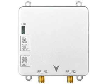
JS-BNK43H-2
A multi-constellation, multi-frequency RTK GNSS module with base/rover dual-mode operation, 1408 hardware channels and dual-antenna heading capability of 0.2° at a 1m baseline. With RTK positioning accuracy of 0.8cm+1ppm horizontal and 1.5cm+1ppm vertical and a built-in dual-core CPU, it suits surveying rovers that must also serve as reference stations, and equipment that needs accurate heading alongside position — such as robotic surveying platforms and mapping vehicles.
JS-BCK43H-3
A multi-constellation RTK GNSS module combining dual-antenna heading (0.2°@1m) with a built-in IMU, RTK accuracy of 8mm+1ppm horizontal and 15mm+1ppm vertical, 60dB anti-interference capability and -160dBm tracking sensitivity. The integrated inertial measurement helps maintain output through short GNSS outages — valuable for machine-guided construction equipment and mobile mapping systems that cannot stop when the sky is briefly obstructed.
JS-SK43H-AH
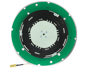
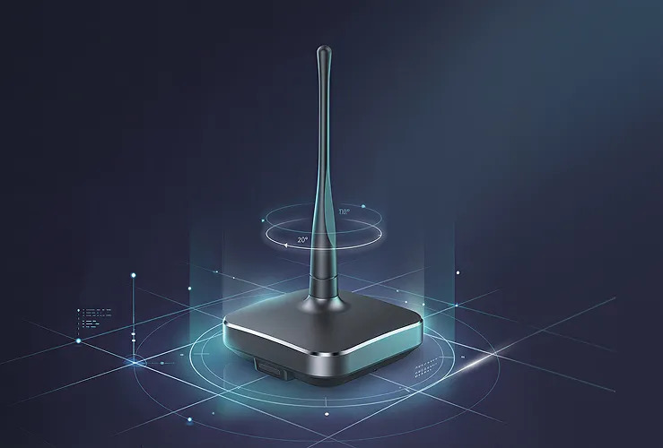
A survey-grade choke ring GNSS antenna with multi-constellation, multi-frequency support, advanced anti-multipath design and high phase-center stability, built for geodetic surveying and reference-station use. On a base station or monitoring point, the choke ring geometry suppresses the reflected signals that corrupt carrier-phase measurements — the exact error source that limits RTK quality in reflective environments.
Building a Complete RTK GNSS Surveying System
An RTK receiver alone is not a surveying system. A complete high-precision setup typically combines a GNSS antenna, an RTK receiver or module, a source of correction data, a controller or software layer, and the surveying equipment itself. The antenna defines measurement quality at the point of signal reception; the receiver processes signals and corrections into coordinates; the correction source — own base station or network service — sets the accuracy baseline; the controller turns coordinates into survey workflow; and the equipment platform carries it all into the field.
The antenna deserves particular emphasis, because it is the component most often treated as an afterthought. A high-performance receiver paired with an unsuitable antenna may not deliver the expected field performance, no matter how capable its RTK engine. For manufacturers designing GNSS surveying equipment, selecting the antenna and receiver together — matched in band coverage, gain and mechanics — is one of the highest-leverage engineering decisions in the entire product. JUMPSTAR's product range includes antennas and receivers designed to be paired this way.
Conclusion
RTK GNSS technology has changed what surveying and mapping teams can expect in the field: centimeter-level positioning when correction data and sky view cooperate, real-time results instead of office surprises, faster data collection, fewer repeated measurements, cleaner digital mapping and more efficient infrastructure surveying. It does not replace careful field practice — satellite visibility, multipath, corrections quality and antenna selection still govern results — but it removes the structural bottleneck of meter-level positioning from professional workflows.
JUMPSTAR provides RTK GNSS modules, OEM boards, receivers, antennas and positioning solutions for surveying and mapping equipment manufacturers and system integrators, with the engineering support to match receiver, antenna and correction strategy to your product. Contact JUMPSTAR to discuss your RTK GNSS requirements for surveying and mapping applications.
.png?imageMogr2/format/webp)
.png?imageMogr2/format/webp)